Chapter 3. Universal robot controller
3.1. Introduction
At the previous decades the industrial robots and NC machines becomes available for smaller companies. Industrial robots has slightly different programming mode than other Industrial machines like CNC machines and Lathes. Programming of NC machines is more standardized (G-code), while different programming languages and interfaces exist for different robots even from the same manufacturer. It is important to follow standards at production, however this standardization is absent in industrial robotics. Despite the standard G code NC machines usually do not have any appropriate port (and sometimes I/O opportunities) for high level communication in a manufacturing cell. Due to these limitations of existing NC and robot controllers, many researches were started to develop a new, open-source, flexible middleware software and hardware architecture for replacing outworn controllers [1, 13].
We are the first in the field of universal control development who are combining the following two popular existing concepts to merge their benefits: the reliable LinuxCNC and the flexible RT-Middleware technology.
The organization of the paper is as follows: Section II describes the origin of LinuxCNC software system. Section III introduces the RT-Middleware technology, Section IV presents three different concepts for hardware architecture, Section V gives an example solution with experimental results, and Section VI concludes the paper.
3.2. RS274NGC G-code standard and LinuxCNC
The US government sponsored Public Domain software systems for numeric control of milling machines were among the very first projects developed with the first digital computers in the 1950`s. In fact, the need and concepts of universal motion controllers is not a novel issue in the industry. The universality was described by modularity, portability, extensibility, and scalability requirements before two decades when the development of LinuxCNC was already started [2]. The project was originally launched by the National Institute of Standards and Technology (NIST) in 1989 [2, 3] and the software was moved under public domain in 2000, allowing external contributors to make changes and reuse the code. The characteristics of universality are still forming an actual topic as the available hardware elements are improved and the control architectures are developed. Today, LinuxCNC is a very reliable and popular open source software system that can be used under General Public License for numerical control.
3.3. Rt-middleware framework
The Japanese Ministry of Economy, Trade and Industry (METI) in collaboration with the Japan Robot Association (JARA) and National Institute of Advanced Industrial Science and Technology (AIST) started a 3 year-national project “Consolidation of Software Infrastructure for Robot Development” in 2002 [4]. An ICE Extension was proposed in [14,15]. With the intention of implementing robot systems to meet diversified users' needs, this project has pursued R&D of technologies to make up robots and their functional parts in modular structure at the software level, and to allow system designers or integrators building versatile robots or systems with relative ease by simply combining selected modular parts. The robot technology middleware have been developed as infrastructure software for implementing the proposed robot architecture, named "OpenRTM-aist" (Open Robot Technology Middleware).
To manage the rapidly growing need for sensor communication in robotic applications several suitable architectures, named middlewares, are being developed for easy system integration. Unfortunately, most of these middleware technologies are developed independently of each other and are often dedicated for specific user applications [5]. RT-Middleware is the only middleware solution that is under standardization [6] and also this solution has proved to be industry ready and used by many industrial partners: Toshiba (different system components), Honda (ASIMO humanoid robot), AIST (OpenHRP humanoid robot, etc.) and also many research institutes. The most important middleware solutions can be found in [7- 11] and a comparison can be found in [11, 12]. The main goal of the middleware system is the development of a common language and control concept for different users and tasks. The base of RT-Middleware concept is that system is build up from low-level, real-time, platform independent components (RTCs, RT-Components). These components are developed for certain machines, sensors and actuators. From these components more complex machine configurations can be made: production cells or an entire production line. The advantage of this architecture is its well-defined hierarchy, modularity, scalability and fast development ability. More details about the RT-middleware can be found in references [9].
3.4. Different architecture concepts
Following chapter describes three different experimental systems for different machines. The first is a joint controller which can be the smallest element of a manufacturing cell and controlled by an RTM server. The second is a compact 3-axis desktop CNC controller, which works as a small plug&play RT-Middleware unit. The third concept is combining the low-level flexibility (able to control different kind of systems on low level) of the LinuxCNC software system and the high-level flexibility (connectable to each other to form a production cell) of the latest RT-Middleware technology.
3.4.1. The first one is a joint controller
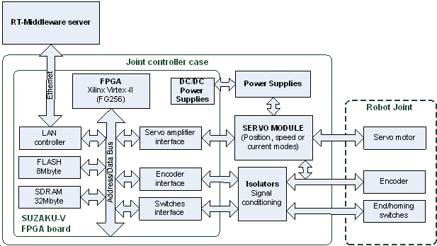
In case there is no hard-real-time attachment necessary between machine joints, it is possible to develop one RT-Middleware RTC hardware and software unit to drive any joint. In this concept more instances of joint component is controlled by a higher level RTC component. Main advantage of this architecture is its flexibility: new joints can be attached or joints can be reconfigured with the reuse of joint RTC hardware and software component. It has certain small delay in control which makes it not fit for example simultaneous movement of high speed CNC machine joints, but it fits to most automation applications like pick&place. An RT-Middleware based joint was developed to test the performance of this concept and get experimental results. Two pieces of this joint controller were manufactured and attached to the first two angular joints of an ADEPT 604-S type SCARA robot. Block diagram of the hardware architecture can be seen on figure IV.1. The logic was implemented in a SUZAKU-V FPGA board. Custom logic and PowerPC processor was configured to run Linux kernel and realize real-time interfaces. The board is connected to the Middleware server via Ethernet. Furthermore the developed electronics includes power amplifier for DC motors, signal conditioning and necessary power converters. It was developed to be the smallest element of a manufacturing cell.
3.4.2. The second one is a simple decentralized CNC controller
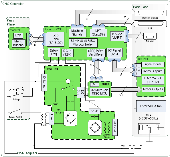
At a 3 axes CNC machine the joints are usually linearly independent. In this case the joint coordinates have effects only on the X, Y and Z coordinates of the TCP. Our decentralized CNC controller can get the joint references from an external PC based G code interpreter. The mechanical design and the shape of the workspace of milling machines can be specialized for different tasks, but the control method can be the same. After the controller and the machine is connected, the position control loops of the axes run on the CNC controller (figure IV.2), and can be tuned via RS232 port from a PC. It is possible to control additional functions along output 8 relays, and 8 isolated inputs, for example coolant, tool size measurements, and other PLC functions. These I/O interfaces can be accessed along ModBus interface. With this system design and a normal PC different CNC machines can be controlled without machine specific controller development. The G code is a common machine language so the PC based RT-Middleware G code interpreter can be used universally. Our decentralized CNC controller is a universal hardware element for these machines so the cost of this concept can be reduced by the increasing number of the manufactured controllers.
3.4.3. Linux based modular multi-axis controller
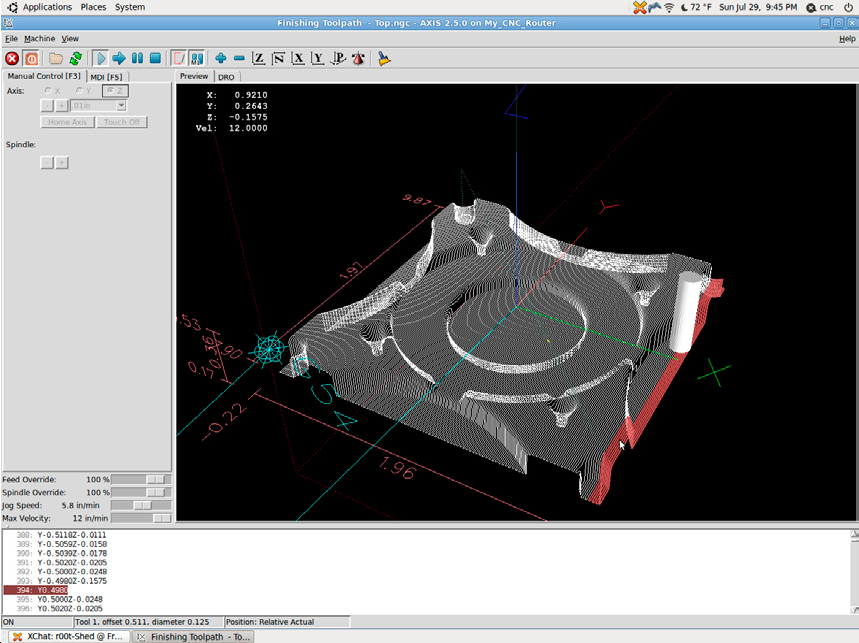
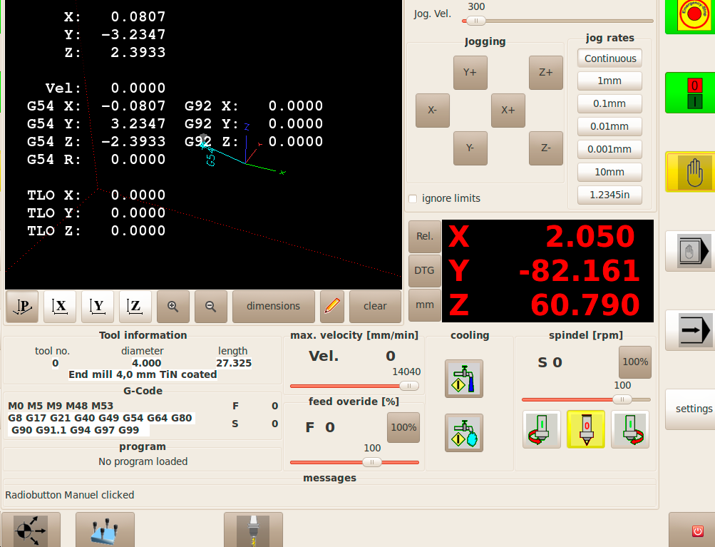
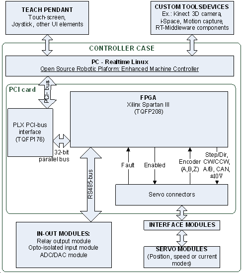
The latest version of our controllers is a complete modular solution for most motion control applications up to 9 axes. The system is based on LinuxCNC, which reliable core was developed since more than two decades, described in the introduction. And we combined this deep experience with modern hardware elements of today's semiconductor industry. This platform is an open-source software system that implements numerical control capability using general purpose computers to control any servo driven machines. It uses Linux kernel with real time extensions (RTAI or RTLinux), and can control up to 9 axes or joints of a machine using standard G-code as input. It can handle the operation of all peripheral machine elements, e.g. tool length measurement, cooling, tool-change procedure, etc. The graphical user interface can be customized for specific kinds of usage e.g. touch screen or interactive development, see figure IV.3. Programming features include most needs of NC usage. It is possible to implement inverse kinematics, hence the software system is capable to control non-Cartesian robots as well. The hardware architecture of the generic system layout can be seen on figure IV.4. The PC installed with LinuxCNC is hosting a PCI card, which is based on a PCI bridge ASIC and an FPGA.
(b)
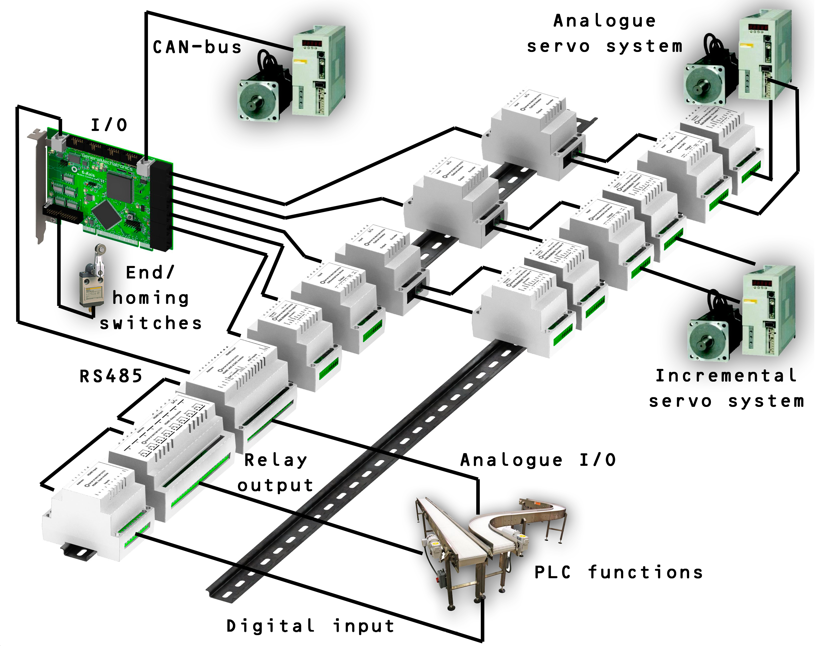
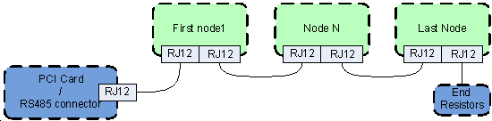
As the LinuxCNC has a simple ladder diagram editor and handles standard PLC functions, the hardware architecture is extended with a RS485 bus for I/O extension modules. The bus is handled by a separate 8-bit RISC microcontroller on the PCI card, which communicates via SPI with the FPGA. Currently digital input, relay output, ADC/DAC, and teach pendant modules are exist. These modules can be connected in chain with a termination resistor at the end of the bus, see figure IV.5./a. Each module has a unique, four bit long address on the bus, hence up to 16 modules can be chained to one PCI card.
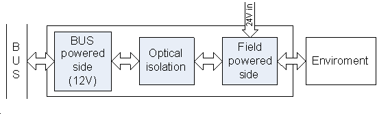
Basically, the modules have a bus powered and a field or application powered side with an optical isolation between them, see figure IV.5./b. But for example an optical isolated input module has only field power side as the inputs from the field are only simple opto-coupler inputs. Each node connected to the bus is recognized by the PCI card automatically. During startup the driver exports pins and parameters of all available modules automatically. All the I/O-s of these modules can be routed to a function in the hardware abstraction layer (HAL) of LinuxCNC, and can be controlled by a custom logic implemented with the ladder editor.
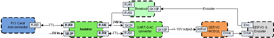
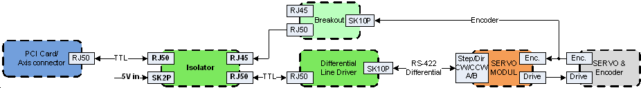
The specialty of the system is in the servo connection interface. A novel modular concept is introduced for connecting different types of servo controllers including the old analogue systems, the incremental systems, and modern CAN based servo modules. Four different small and simple axis-interface modules were developed, and combining them in many different ways makes the possibility of interfacing with a servo controller. These types are optical isolator, DAC module, differential line driver, and a breakout for simple terminal connection. Figure IV.6. shows only two different servo examples from the possible 8: a analogue, and an incremental with differential outputs and encoder feedback.
3.5. Example solution
This chapter presents an application to multi-axis simultaneous control. LinuxCNC was connected to a SCARA type robot. The theoretical background of the implemented control algorithm is described in point A). The modular hardware structure resulted a flexible system which can be connected to any similar machines without long time demanding hardware development (described in point B).
3.5.1. Kinematics of the experimental non-Cartesian system
Three different universal architectures were introduced from which two were connected to a SCARA type robot. This chapter describes the implemented SCARA kinematics (Fig. V.1.) which is followed by hardware and driver-level software description of an experimental systems.
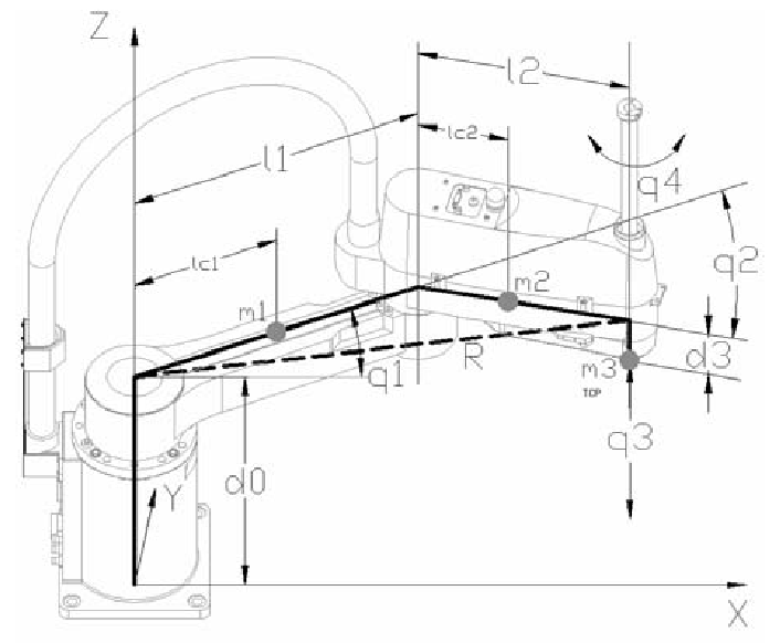
The Cartesian coordinates of TCP can be expressed as equation (5.1), (5.2), (5.3).
|
|
(5.1) |
|
|
(5.2) |
|
|
(5.3) |
Forward kinematics can be expressed deriving equations (5.1), (5.2) as (5.4),(5.5).
|
|
(5.4) |

|
|
(5.5) |

The connection between the Cartesian velocities and joint velocities can be represented as equation (5.6).
|
|
(5.6) |

Where

Where  is a Jacobean matrix as equation (5.7)
|
|
(5.7) |
3.5.2. Application example
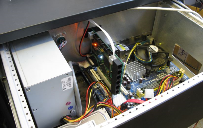
At a manufacturing line an assembler or palletizing cell is usually indispensable. The most common palletizing type robot is the SCARA. The LinuxCNC has a kinematic module, which software part is open source as well. We designed the kinematic module for a SEIKO D-TRAN TT 4000SC SCARA robot. The original controller was broken and obsolete, but the mechanics of the machine worked perfectly. Our controller has a modular built up, so the main parts of the system are separated in three shelves. The first one is universal for most kind of machines which is the PC and the PCI card. (Fig.V.2.a) The machine specific signals (end- and homing- switches), the RS485 bus, and the CAN references are also connected to this part of the controller.
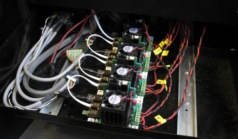
The second shelf contains the modular components, which is chosen for the specific machine. In this case these are the DC power amplifiers and the RS485 modules. (Fig.V.2.b) (These can be digital and analogue I/O-s.) The power amplifiers are connected to the DC bus, to DC logic power, to CAN references and to the encoders. The motor parameters, the encoder parameters and control loops at the power amplifiers can be tuned and measured via USB.
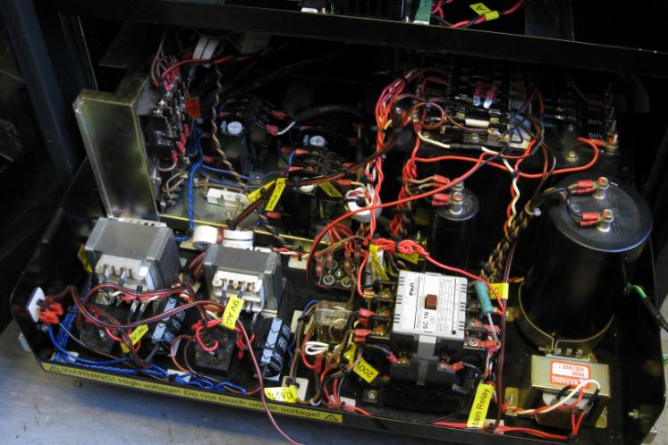
The third shelf contains the power electronics. (Fig.V.2.c) These elements are mainly saved from the original controller. It has an E-Stop circuit, fuses, DC powers, brake resistors and thermal protection. With this concept we could save and modernize the original robot mechanics (and some of the power electronics). The machine can be integrated into a modern and flexible manufacturing line as a palletizing cell. According to the modular built up of the controller we could use the SCARA robot again without any long time demanding electronic and software development. As a part of the system we also developed a teach pendant with touch screen and joysticks for the X,Y,Z and rotZ jogging. The controller has standard Ethernet, USB, etc. interfaces. With the LinuxCNC RT-Middleware component the robot can be connected and integrated into a high level manufacturing control system.
3.6. Conclusion for the universar robot controller
The LinuxCNC & RT-Middleware based modular control system was implemented with success for more machines now: Two 3-axes desktop CNC, a 3-axes dental CNC, a 5-axes with tool-change and tool-length measurement, and at least two SCARA robots. All of these machines can be connected along the RTM interface of the LinuxCNC and can work together in real-time applications. The improvement of the modules and all other hardware elements was in progress with every system integration. The first controller was running since more than one year with negligible maintenance now, showing that the system is reliable too. The application was started by external international system integrators in Europe this year.
3.7. References for the Universal robot controller
Bence Kovács, Géza Szayer, Ferenc Tajti, Solvang Bjorn, Péter Korondi, Design of a universal robot controller Robi, International Engineering Symposium at Bánki (IESB 2011). Budapest, Hungary, pp. 1-13, 2011.11.15.
Proctor, F. M., and Michaloski, J., "Enhanced Machine Controller Architecture Overview," NIST Internal Report 5331, December 1993. Available online at ftp://129.6.13.104/pub/NISTIR_5331.pdf
Albus, J.S., Lumia, R., “The Enhanced Machine Controller (EMC): An Open Architecture Controller for Machine Tools,” Journal of Manufacturing Review, Vol. 7, No. 3, pp. 278–280, September 1994.
Bence Kovács, Géza Szayer, Ferenc Tajti, Péter Korondi, István Nagy: "Robot with dog type behavior”, 17th Int. Conference on Electrical Drives and Power Electronics The High Tatras, Slovakia 28–30 September, 2011
Kotoku, Tetsuo: "Robot Middleware and its Standardization in OMG" in International Conference on Intelligent Robots and Systems (IROS'06) Workshop on Robotic Standardization, Beijing, China, 11-13 Oct. 2006
J.U. Cho, Q.N. Le and J.W. Jeon, An FPGA-Based Multiple-Axis Motion Control Chip, IEEE Trans. Ind. Electron., Vol. 56, No. 3, pp. 856-870, Mar. 2009.
Ozaki Fumio, Oaki Junji, Hashimoto Hideaki, Sato Hirokazu, "Open Robot Controller Architecture (ORCA)" in Journal: Nippon Kikai Gakkai Robotikusu, Mekatoronikusu Koenkai Koen Ronbunshu, Vol. 2, 2003.
M. Mizukawa, H. Matsuka, T. Koyama, T. Inukai, A. Noda, H. Tezuka, Y. Noguchi, N. Otera, "ORiN: open robot interface for the network - the standard and unified network interface for industrial robot applications" in Proceedings of the 41st SICE Annual Conference (SICE 2002), Tokyo, Japan, Vol. 2, pp. 925- 928, Aug. 2002.
N. Ando, T. Suehiro, K. Kitagaki, T. Kotoku, Yoon Woo-Keun, “RT-middleware: distributed component middleware for RT (robot technology)” in Proceedings of 2005 IEEE/RSJ International Conference on Intelligent Robots and Systems (IROS 2005), pp. 3933- 3938, ISBN: 0-7803-8912-3, 2-6 Aug. 2005.
G. Veiga, J. N. Pires,K. Nilsson “On the use of SOA platforms for industrial robotic cells” in Proceedings of Intelligent Manufacturing Systems (IMS2007), Spain, 2007.
J.-C. Baillie, “URBI: towards a universal robotic low-level programming language” in Proc. of IEEE/RSJ International Conference on Intelligent Robots and Systems (IROS 2005), pp. 820- 825, ISBN: 0-7803-8912-3, 2-6 Aug. 2005.
B. Solvang, G. Sziebig, and P. Korondi, “Multilevel control of flexible manufacturing systems,” in Proc. IEEE Conference on Human System Interactions (HSI’08), pp. 785– 790, 2008.
Solvang Bjørn, Refshal Lars Kristian, Sziebig Gábor “STEP-NC Based Industrial Robot CAM System.” In: 9th IFAC Symposium on Robot Control (SYROCO2009). Gifu, Japán, 2009.09.09-2009.09.12. (IFAC) Gifu: IFAC by Pergamon Press, pp. 361-366.
Zoltán Krizsán, “ICE Extension of RT-Middleware Framework”, in Proceedings of 10th International Symposium of Hungarian Researchers on Computational Intelligence and Informatics, pp 513-521, 2009.
Zoltán Krizsán, Szilveszter Kovács: Structural Improvements of the OpenRTM-aist Robot Middleware, Applied Computational Intelligence in Engineering and Information Technology Topics in Intelligent Engineering and Informatics, Eds: R.E. Precup, S. Kovács, S. Preitl and E.M. Petriu, 2012, Volume 1, pp. 287-300, ISBN: 978-3-642-28304-8