Chapter 9. PCI universal motion control system
9.1. Introduction
This manual gives instructions and technical information for system integration of the General Mechatronics PCI motion control system. The system is suitable for many servo applications like robots, CNC machines, latches, plasma cutters etc. It can be easily integrated into LinuxCNC for a complete machine control solution. (PC based motion control system. For more information, please visit the LinuxCNC official website: http://www.linuxcnc.org/)
9.2. Features and interfaces
The PCI motion control card is based on a FPGA and a PCI bridge interface ASIC. There are connectors on the whole border of the card to interface with the majority of possible system elements that can be found in an automated robotic cell.
There are six RJ50 modular axis connectors at the inner edge of the card in order to drive incremental or classic analogue servos. Four different small DIN-rail mounted axis modules are available to make possible to drive six different servo configurations in a cost effective way. The interface can be made with an exact combination of the suitable axis modules for the actual servo configuration. (See chapter 3.1.1. for the possible servo types and configurations.)
A CAN bus interface can be seen at the top edge from the right side (RJ12 modular connector): this is for modern digital servo systems which are communicating on CAN-bus.
Then in the middle, four times eight general purpose I/O pins are placed on standard flat cable headers. These bare I/O pins can be configured in LinuxCNC for any custom purpose. In most cases an optical isolation is advisable here to prevent the PCI card and the PC from disturbances and unsafe voltage transients coming from the industrial environment.
On the left side of the top edge an RS485 bus was designed to interface with compact DIN-rail mounted expander modules. An 8-channel digital input, an 8-channel relay output and an analogue I/O (4x 10 Volts output and 8x 5 Volts input) modules are available now. Maximum 16 modules can be connected to the bus altogether.
At the end, on the bottom, there is a 26 pin flat cable header with 20 optically isolated input pins. Six times three for the direct connection of two end switches and one homing sensor for each axis. Additionally, two optically isolated E-stop inputs are available.
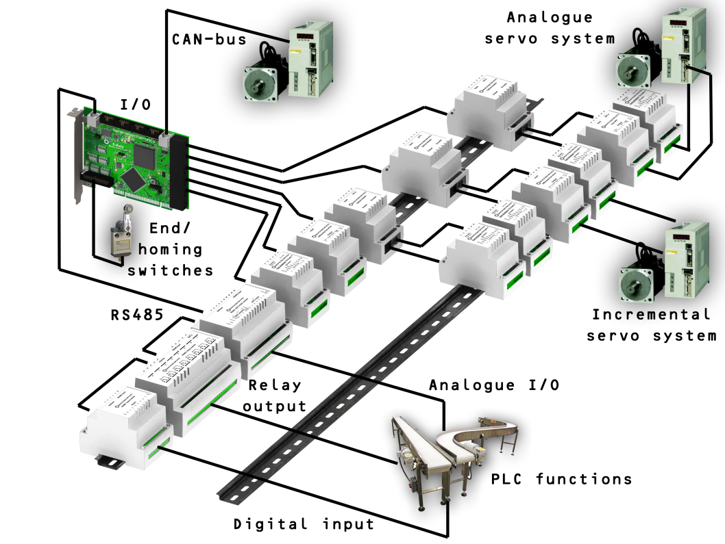
With these functions a small automated manufacturing cell can be successfully controlled with a short time system integration procedure. The following figure demonstrates the typical connection of devices related to the control system.