Chapter 12. HAL settings
In this chapter, all the relevant system relevant hall settings can be found, except for the modules on the RS485 bus. Those can be found in the next chapter for each module.
All the pins and parameters of this chapter are updated by the following two functions:
gm.<nr. of card>.read
gm.<nr. of card>.write
Both should be added to the servo thread in this given order (first read then write) for most applications.
12.1. Encoder
The motion control card has six encoder modules. Each encoder module has three channels:
Channel-A
Channel-B
Channel-I (index).
The encoder is able to count quadrature encoder signals or step/dir signals. Each encoder module is connected to the inputs of the corresponding RJ50 axis connector.
Every encoder pin and parameter name begins as follows:
gm.<nr. of card>.encoder.<nr of axis>,where <nr of axis> is form 0 to 5.
For example: gm.0.encoder.0.position►refers to the position of the encoder module of axis 0.
The PCI card counts the encoder signal independently from LinuxCNC.
HAL pins are updated by the gm.<nr of card>.read function.
12.1.1. Pins:
.reset(bit, In)► When True, resets counts and position to zero.
.rawcounts(s32, Out)► The raw count is similar to the counts, but unaffected by reset or the index pulse.
.counts(s32, Out)► Position in encoder counts.
.position(float, Out)► Position in scaled units (=.counts/.position-scale).
.index-enabled(bit, IO) ►When True, counts and position are rounded or reset (depends on index-mode) on next rising edge of channel-I. Every time position is reset because of Index, the index-enabled pin is set to 0 and remain 0 until the connected HAL pin does not set it.
.velocity (float, Out) ► Velocity in scaled units per second. GM encoder uses high frequency hardware timer to measure the time between encoder pulses in order to compute velocity. It greatly reduces quantization noise as compared to simply differentiating the position output. When the measured velocity is below min-velocity-estimate, the velocity output is 0.
12.1.2. Parameters:
.counter-mode(bit, R/W)► When True, the counter counts each rising edge of the channel-A input to the direction determined by channel-B. This is useful for counting the output of a single channel (non-quadrature) or step/dir signal sensor. When false, it counts in quadrature mode.
.index-mode(bit, R/W)► When True and .index-enabled is also true, .counts and .position are rounded (based on .counts-per-rev) at rising edge of channel-I. This is useful to correct few pulses error caused by noise. In round mode, it is essential to set .counts-per-rev parameter correctly. When .index-mode is False and .index-enabled is true, .counts and .position are reset at channel-I pulse.
.counts-per-rev(u32, R/W)► Determine how many counts are between two index pulses. It is used only in round mode, when both .index-enabledand.index-mode parameters are True. GM encoder process encoder signal in 4x mode, so for example in case of a 500 CPR encoder it should be set to 2000. This parameter can be easily measured by setting .index-enabledtoTrue and .index-mode to False (so that .counts resets at channel-I pulse), than move the axis by hand and see the maximum magnitude of .counts pin in halmeter.
.index-invert(bit, R/W)► When True, channel-I event (reset or round) occur on the falling edge of channel-I signal, otherwise on the rising edge.
.min-speed-estimate(float, R/W)► Determine the minimum measured velocity magnitude at which .velocity will be set as nonzero. Setting this parameter too low will cause it to take a long time for velocity to go to zero after encoder pulses have stopped arriving.
.position-scale(float, R/W)►Scale in counts per length unit. .position=.counts/.position-scale. For example, if position-scale is 2000, then 1000 counts of the encoder will produce a position of 0.5 units.
12.1.3. HAL example
Setting encoder module of axis 0 to receive 500 CPR quadrature encoder signal and use reset to round position:
setp gm.0.encoder.0.counter-mode 0# 0: quad, 1: stepDir
setp gm.0.encoder.0.index-mode 1# 0: reset pos at index, 1:round pos at index
setp gm.0.encoder.0.counts-per-rev 2000# GM process encoder in 4x mode, 4x500=2000
setp gm.0.encoder.0.index-invert 0
setp gm.0.encoder.0.min-speed-estimate 0.1#in position unit/s
setp gm.0.encoder.0.position-scale 20000#in case of 10 encoder revolutions cause the machine to move one position unit (10x2000)
Connect encoder position to LinuxCNC position feedback:
net Xpos-fb gm.0.encoder.0.position => axis.0.motor-pos-fb
12.2. Stepgen module
The motion control card has six stepgen modules, one for each axis. Each module has two output signals. It can produce Step/Direction, Up/Down or Quadrature (A/B) pulses. Each stepgen module is connected to the pins of the corresponding RJ50 axis connector.
Every stepgen pin and parameter name begins as follows:
gm.<nr. of card>.stepgen.<nr of axis>, where nr of axis is from 0 to 5.
For example: gm.0.stepgen.0.position-cmd►refers to the position command of stepgen module of axis 0 on card 0.
The PCI card generates step pulses independently from LinuxCNC. HAL pins are updated by gm.<nr of card>.write function.
12.2.1. Pins:
.enable(bit, In)► Stepgen produces pulses only when this pin is true.
.count-fb(s32, Out)► Position feedback in count units.
.position-fb(float, Out)► Position feedback in position units.
.position-cmd(float, In)► Commanded position in position units.
Used in position mode only.
.velocity-cmd(float, In)► Commanded velocity in position units per second.
Used in velocity mode only.
12.2.2. Parameters:
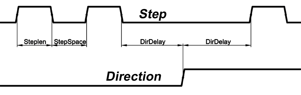
.step-type(u32, R/W)►When 0, the module produces Step/Dir signal.
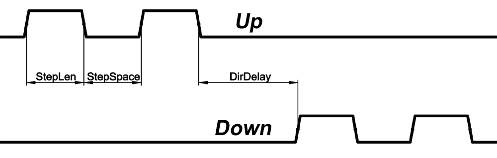
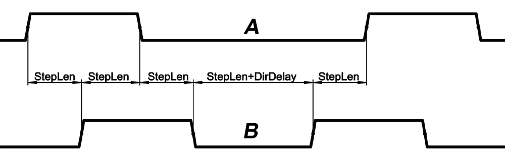
When 1, it produces Up/Down step signals. And when it is 2, it produces quadrature output signals.
.control-type(bit, R/W)►When True, .velocity-cmd is used as reference and the velocity control computes pulse rate output. When False, .position-cmd is used as reference and position control calculate pulse rate output.
.invert-step1(bit, R/W)►Invert the output of channel 1.
(Step signal in StepDir mode)
.invert-step2(bit, R/W)►Invert the output of channel 2.
(Dir signal in StepDir mode)
.maxvel(float, R/W)► Maximum velocity in position units per second.
If it is set to 0.0, .maxvel parameter is ignored.
.maxaccel(float, R/W)►Maximum acceleration in position units per second squared. If it is set to 0.0, .maxaccel parameter is ignored.
.position-scale(float, R/W)►Scale in steps per length units.
.position-fb=.count-fb/.position-scale. For example, if position-scale is 1000, then 1 position unit command produces 1000 step pulses.
.steplen(u32, R/W)►Length of step pulse in nano-seconds.
.stepspace(u32, R/W)►Minimum time between two step pulses in nano-seconds.
.dirdelay(u32, R/W)►Minimum time between step pulse and direction change in nano-seconds.
In order to evaluate the appropriate values see the timing diagrams below:
12.2.3. HAL example:
Setting stepgen module of axis 0 to generate 1000 step pulse per position unit:
setp gm.0.stepgen.0.step-type 0# 0:stepDir,1:UpDown,2:Quad
setp gm.0.stepgen.0.control-type 0# 0:Pos. control, 1:Vel. control
setp gm.0.stepgen.0.invert-step1 0
setp gm.0.stepgen.0.invert-step2 0
setp gm.0.stepgen.0.maxvel 0# do not set maxvel for the step generator, let the interpolator control it.
setp gm.0.stepgen.0.maxaccel 0# do not set max acceleration for the step generator, let the interpolator control it.
setp gm.0.stepgen.0.position-scale 1000# 1000 step/position units
setp gm.0.stepgen.0.steplen 1000 # 1000 ns = 1 us
setp gm.0.stepgen.0.stepspace1000# 1000 ns = 1 us
setp gm.0.stepgen.0.dirdelay 2000# 2000 ns = 2 us
Connect stepgen to axis 0 position reference and enable pins:
net Xpos-cmd axis.0.motor-pos-cmd => gm.0.stepgen.0.position-cmd
net Xen axis.0.amp-enable-out => gm.0.stepgen.0.enable
12.3. Axis DAC (digital-to-analogue converter)
The motion control card has six serial axis DAC driver modules, one for each axis. Each module is connected to the pin of the corresponding RJ50 axis connector.
Every axis DAC pin and parameter name begins as follows:
gm.<nr. of card>.dac.<nr of axis>,where nr of axis is from 0 to 5.
For example:gm.0.dac.0.value►refers to the output voltage of DAC module of axis 0.
HAL pins are updated by gm.<nr of card>.write function.
12.3.1. Pins:
.enable(bit, In)►Enable DAC output. When enable is false, DAC output is 0.0 V.
.value(float, In)► Value of DAC output in Volts.
12.3.2. Parameters:
.offset(float, R/W)►Offset is added to the value before the hardware is updated
.high-limit(float, R/W)►Maximum output voltage of the hardware in volts.
.low-limit(float, R/W)►Minimum output voltage of the hardware in volts.
.invert-serial(float, R/W)►PCI card is communicating with DAC hardware via fast serial communication to highly reduce time delay compared to PWM. DAC module is recommended to be isolated which is negating serial communication line. In case of isolation, leave this parameter to default (0), while in case of none-isolation, set this parameter to 1.
12.4. Enable and Fault signals
The PCI motion control card has one enable output and one fault input HAL pins, both are connected to each RJ50 axis connector and to the CAN connector.
HAL pins are updated by gm.<nr of card>.read function.
12.4.1. Pins:
gm.<nr of card>.power-enable(bit, In)►If this pin is True,
and Watch Dog Timer is not expired
and there is no power fault
Then power enable pins of axis- and CAN connectors are set to high, otherwise set to low.
gm.<nr of card>.power-fault(bit, Out)►Power fault input
12.5. Watchdog timer
Watchdog timer resets at gm.<nr of card>.read function.
12.5.1. Pins:
gm.<nr of card>.watchdog-expired(bit, Out)►Indicates that watchdog timer is expired.
Watchdog timer overrun causes the set of power-enable to low in hardware.
12.5.2. Parameters:
gm.<nr of card>.watchdog-enable(bit, R/W)►Enable watchdog timer.
It is strongly recommended to enable watchdog timer, because it can disable all the servo amplifiers by pulling down all enable signal in case of PC error.
gm.<nr of card>.watchdog-timeout-ns(u32, R/W)►Time interval in which the gm.<nr of card>.readfunction must be executed. The gm.<nr of card>.read is typically added to servo-thread, so watch timeout is typically set to 3 times the servo period.
12.6. GM-CAN
The motion control card has a CAN module to drive CAN servo amplifiers. Implementation of higher level protocols like CAN open is further development. Currently GM produced power amplifiers have upper level drivers which export pins and parameters to HAL. They receive position reference and provide encoder feedback via CAN bus.
Every CAN pin and parameter name begins as follows:
gm.<nr. of card>.can-gm.<nr of axis>,where <nr of axis> is from 0 to 5.
For example:gm.0.can-gm.0.position►refers to the output position of axis 0 in position units.
HAL pins are updated by gm.<nr of card>.write function.
12.6.1. Pins:
.enable(bit, In)►Enable sending position references
.position-cmd(float, In)►Commanded position in position units.
.position-fb(float, Out)►Feed back position in position units.
12.6.2. Parameters:
.position-scale(float, R/W)►Scale in per length units.
.position-fb=.encoder-counts/.position-scale. For example, if position-scale is 1000, then 2000 encoder pulses on GM power amplifier produces 2 on position-fb pin.
12.7. Home and Limit switches
The PCI motion control card has two limit- and one homing switch input for each axis. All the names of these pins begin as follows:
gm.<nr. of card>.axis.<nr of axis>,where nr of axis is from 0 to 5.
For example:gm.0.axis.0.home-sw-inindicates the state of the axis 0 home switch.
HAL pins are updated by gm.<nr of card>.read function.
12.7.1. Pins:
.home-sw-in(bit, Out)► Home switch input
.home-sw-in-not(bit, Out)► Negated home switch input
.neg-lim-sw-in(bit, Out)► Negative limit switch input
.neg-lim-sw-in-not(bit, Out)► Negated negative limit switch input
.pos-lim-sw-in(bit, Out)► Positive limit switch input
.pos-lim-sw-in-not(bit, Out)► Negated positive limit switch input
12.8. Emergency stop input signals
In addition to home and limit switches, there are two emergency stop (E-Stop) inputs to detect if the E-Stop button is pressed.
12.8.1. Pins:
gm.0.estop.0.in-0(bit, Out)► Estop 0 input
gm.0.estop.0.in-not-0(bit, Out)► Negated Estop 0 input
gm.0.estop.0.in-1(bit, Out)► Estop 1 input
gm.0.estop.0.in-not-1(bit, Out)► Negated Estop 1 input
12.9. General purpose I/O
The GM 6 axis motion control card has 4 general purpose I/O (GPIO) connectors, with eight configurable I/O c onnectors on each.
Every GPIO pin and parameter name begins as follows:
gm.<nr. of card>.gpio.<nr of gpio con>,where <nr of gpio con> is from 0 to 3.
For example:gm.0.gpio.0.in-0 indicates the state of the first pin of the first GPIO connector on the PCI card.
HAL pins are updated by gm.<nr of card>.read function.
12.9.1. Pins:
.in-<0-7>(bit, Out)►Input pin
.in-not-<0-7>(bit, Out)►Negated input pin
.out-<0-7>(bit, In)►Output pin. Used only when GPIO is set to output.
12.9.2. Parameters:
.is-out-<0-7>(bit, R/W)►When True, the corresponding GPIO is set to the totem-pole output, other wise is set to high impedance input.
.invert-out-<0-7>(bit, R/W)►When True, the pin value will be inverted. Is used when the pin is configured as output.